

Bell Ringer
Instructions: Select one of the Bell Ringers for students to reflect on and answer.
Vocabulary List
Instructions: Go over important terms and their definitions before watching the Science of Electricity video. The student vocabulary list can be found in the Student Guide and Science of Electricity- Starter Pack.
| Word | Definition | Example |
|---|---|---|
| Silicon | noun; A natural element from sand and rocks that can act as a semiconductor, used in electronics and solar panels to help turn sunlight into electricity. | “This [way] uses silicon – like in a computer chip – to turn light into electricity.” |
| Computer chip | noun phrase; a tiny electronic part typically made of silicon that processes or stores information in computers and other devices | “This [way] uses silicon – like in a computer chip – to turn light into electricity.” |
| Generator | noun; a machine that converts mechanical energy into electrical energy | “The other 99% comes from generators.” |
| Copper | noun; a metal that easily conducts electricity and is used in wires and motors | “A generator is just magnets surrounding a core of coil wire, usually copper.” |
| Coil | noun; a loop or series of loops of wire, often used in electric devices to create a magnetic field | “The coil turns within the generators and makes electricity…” |
| Turbine | noun; a machine that spins when water, air or steam flows through it to generate electricity | “Water makes steam, and steam turns the turbine.” |
Quiz
Instructions: Review key concepts after watching the Science of Electricity video. The Student Guide and Science of Electricity – Starter Pack contain the quiz and cloze notes. Click here to play the Kahoot!
Answer Key: Q1:C Q2:B Q3:C Q4:C
Reading
Instructions: Provide students with the Science of Electricity – Reading info sheet for an in-depth exploration of the topic.
Reading Answer Key:
- Electrons.
- Protons are stuck inside the nucleus of the atom and cannot move around in a circuit.
- A conductor is a material that allows electrons to move easily through it. Examples: copper, aluminum, silver.
- Volts (V).
- Voltage is the push that moves electrons; current is how many electrons flow through the circuit each second.
- The resistance will increase.
- The whole circuit will stop working because the path is broken.
- Because if one branch stops working, the others still work, and every device gets the full voltage from the power source.
- The total resistance goes down.
- Resistance slows down the movement of electrons.
- Answers will vary. Example from text: voltage is like water pressure in a hose.
- A. I = V ÷ R = 12 ÷ 4 = 3 amps
B. V = I × R = 3 × 5 = 15 volts
C. R = V ÷ I = 24 ÷ 6 = 4 ohms
Reading Answer Key (Higher Complexity Questions):
- Electricity is the movement of electrons (negatively charged particles) through a conductor.
- Protons are locked inside the nucleus of atoms and cannot move, so they do not contribute to current in circuits.
- Voltage is like pressure from crowding electrons together—more packed-in electrons means more pressure to move.
- Current is the flow of electric charge. One amp means one coulomb of charge passes through a point each second.
- Resistance is the opposition to current flow. It is measured in ohms (Ω).
- Conductors: copper, aluminum. Insulators: rubber, plastic.
- A longer wire increases resistance because electrons encounter more obstacles over a greater distance.
- A complete circuit provides a continuous path for electrons. If it is broken, current cannot flow and the device won’t work.
- Adding components to a series circuit increases total resistance and decreases the total current.
- Adding branches to a parallel circuit decreases total resistance and increases the total current.
- In a series circuit, voltage is shared across components. In a parallel circuit, each branch receives the full voltage.
- Parallel circuits are better for household lighting because each device works independently. If one fails, others still operate.
- Ohm’s Law relates voltage (V), current (I), and resistance (R) in the formula V = I × R.
- Increasing voltage increases current, as long as resistance stays constant.
- In a series circuit, adding more devices increases resistance, reducing current. Less current means dimmer bulbs.
- Parallel circuits are more reliable because each device has its own path to the power source. If one fails, the others stay on.
- A. V = I × R = 3 A × 10 Ω = 30 V
B. I = V ÷ R = 24 V ÷ 6 Ω = 4 A
C. R = V ÷ I = 18 V ÷ 3 A = 6 Ω - In a series circuit, current is the same through all components, voltage is divided, and resistance adds up. In a parallel circuit, voltage is the same across all branches, current divides, and total resistance decreases as more branches are added.
Computation
Instructions: Provide students with the Science of Electricity – Computation activity for math integration and practice.
Reference Table
| Energy Source | Typical Performance Metric (%) | Power Plant Operation Cost per kWh Produced ($) | CO2 Emissions During Generation (lb/kWh) |
|---|---|---|---|
| Coal | 33% thermal efficiency | $0.0220 | 0.74 |
| Natural Gas | 50% thermal efficiency | $0.0220 | 0.40 |
| Nuclear | 33% thermal efficiency | $0.02219 | 0 |
| Hydropower | 35% capacity factor | $0.01471 | 0 |
| Wind | 35% capacity factor | $0.02647 | 0 |
| Solar PV | 24% capacity factor | $0.02647 | 0 |
Sources: EIA; PCI Energy Solutions; EIA; EIA; EIA
Answer Key:
Q1: 150 million / 0.33 ≈ 454.5 million kWh → 454.5M / 293 ≈ 1.55 million MMBtu
Q2: 1.55 million MMBtu × $2.50 = $3.875 million
Q3: Coal: 150M × 2.3 = 345M lbs; Natural Gas: 150M × 1.0 = 150M lbs; Difference = 195M lbs less from gas
Q4: Nuclear: 75M kWh, Wind: 45M kWh, Solar: 30M kWh
Q5: 500M × 0.20 = 100M kWh produced
Q6: Hydropower is most efficient at 90% and requires no fuel; it’s the best choice to minimize fuel input. The second-best option is wind, with 45% efficiency and also no fuel required.
Data Set
Instructions: Provide students with the Science of Electricity – Data Set for data literacy and analysis practice.
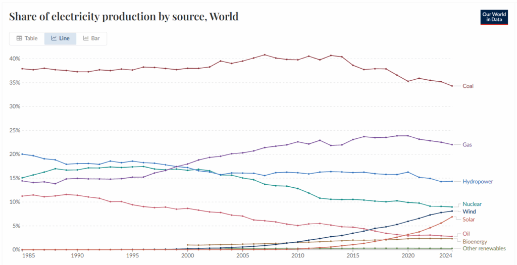
Note: “Other renewables” include geothermal, wind, and tidal.
Data Table
| Coal | Gas | Hydro-power | Nuclear | Wind | Solar | Oil | Bio-energy | Other Renew-ables | |
|---|---|---|---|---|---|---|---|---|---|
| 1990 | 37.29% | 14.95% | 18.05% | 16.73% | 0.03% | <0.01% | 11.42% | ||
| 2010 | 39.78% | 22.61% | 16.12% | 12.82% | 1.63% | 0.15% | 5.07% | 1.54% | 0.28% |
| 2024 | 34.32% | 22.03% | 14.32% | 8.96% | 8.09% | 6.91% | 2.78% | 2.31% | 0.29% |
Answer Key:
Question 1: Answers will vary. (Example: Many countries still rely on existing coal infrastructure; it’s relatively cheap and abundant, and transitioning takes time and investment.)
Question 2: Answers will vary. (Example: Wind and solar are newer technologies, require high upfront costs, depend on weather conditions, and may lack sufficient grid or storage support.)
Question 3: Answers will vary. (Example: Coal, oil, and nuclear have declined. Reasons may include environmental concerns, decommissioning of old plants, safety concerns (especially nuclear), and competition from cheaper sources, or sources with lower emissions.)
Question 4: Answers will vary. (Example: Likely wind or solar, due to falling costs, international climate goals, and improved technologies of solar panels and/or wind turbines, and energy storage capacity.)
Question 5: Answers will vary. (Example: Economically, some sources are cheaper or subsidized. Politically, countries may want energy independence or to meet international agreements. Environmentally, there’s pressure to reduce emissions and pollution.)
How Windings Affect Voltage Lab
Instructions: Use the How Windings Affect Voltage Lab – Student Handout and the following Teacher Guide to conduct the lab activity.
Introduction
This lab activity introduces students to the principle of electromagnetic induction by exploring how the number of coil windings affects the voltage generated when a magnet moves through a wire coil. It builds foundational understanding of how mechanical energy is transformed into electrical energy, simulating the operation of electric generators. By analyzing how voltage output varies with coil turns, students gain insight into energy transfer and real-world electricity generation systems.
Materials
(per student group)
- Student Handout
- 1 neodymium magnet
- 3-5 feet of copper wire (30 gauge)
- Coil form (plastic tube, spool, or cardboard)
- Voltmeter or multimeter
- Fine grit sandpaper
- Tape/marker/ruler
- Wooden skewer, dowel, or chopstick
- Optional: graphing paper, or digital graphing tool
Student Objectives
Students will be able to
- Construct an electromagnetic coil and accurately measure induced voltage using a voltmeter.
- Investigate and explain the relationship between the number of coil windings and the voltage generated.
- Graph and interpret data to identify trends in voltage production based on coil configuration.
- Connect experimental results to real-world applications of energy generation in systems like electric generators and power plants.
Procedure:
- Divide the class into groups of 2-3 students, and provide each student group with the Student Handout and materials needed for the experiment.
- Important: Demonstrate safe handling of strong magnets.
- Assign each group a different number of windings to avoid overlap and over a wide range (e.g. 50, 100, 150, 200, etc.)
- Students will follow instructions on the Student Handout to conduct the experiment, record data, and answer analysis and reflection questions.
Assessment
Check for accurate data collection and averaging, review graphs for appropriate labeling and scaling, and use the analysis questions on the Student Handout for formative assessment of understanding.
Lab Rubric (also included in Student Handout)
| Category | Excellent | Proficient | Developing | Needs Improvement |
|---|---|---|---|---|
| Lab Setup and Participation | Students prepared materials, followed procedure accurately, and actively participated in all aspects of the lab. | Students followed directions mostly independently and accurately, and actively participated in most steps. | Students needed some reminders to stay on task, use materials correctly, and actively participate. | Students did not engage meaningfully, use materials correctly, or required frequent redirection. |
| Data Collection | Data is complete, accurate and neatly recorded in the table, with multiple trials included. | Data is mostly complete and accurate with minor errors or omissions. | Some data is missing or inconsistent; limited number of trials | Data is incomplete, disorganized, or missing altogether. |
| Analysis Questions | All questions are answered thoroughly with clear explanations and reasoning. | Most questions are answered with appropriate reasoning. | Some answers are incomplete or lack depth. | Responses are missing or show little understanding. |
| Optional: Graphing | The graph is neat and correctly labeled with title, axes, units, and accurately plotted data. | The graph includes most labels and data points are reasonably plotted. | Graph is missing labels or contains several plotting errors. | Graph information is unclear, missing or mostly incorrect. |
Analysis Questions Answer Key:
- As the number of coil windings increased, the average voltage produced also increased.
- Increasing the number of turns increases the total length of wire that cuts through the changing magnetic field. According to Faraday’s Law of Electromagnetic Induction, a larger total magnetic field change across the coil produces a higher induced voltage.
- The motion of the magnet represents mechanical energy (movement). The mechanical energy is transformed into electrical energy in the coil through electromagnetic induction. The faster and smoother the motion, the more energy is transferred.
- This experiment is a small-scale model of how generators work in power plants; moving magnets relative to coils of wire to produce electricity. In real power plants, turbines spin the coil or magnets continuously using wind, falling water, or steam from burning fuel or nuclear heat.
- Other variables that affect voltage include the strength of the magnet, the speed of magnet motion, and the coil diameter. In another experiment, the number of turns could be kept the same, while magnets of different strengths are tested and voltage measured.
- Using a coil with many turns of wire would increase voltage output; making sure the wire is wound tightly and neatly to maximize efficiency; use a strong magnet and ensure minimal gaps between the moving magnet and the coil.
- The voltmeter allowed for precise, quantitative measurement of voltage, otherwise invisible to the naked eye. It ensured the data collected was consistent, making it possible to compare results between trials and groups.
PhET Lab Extension – Faraday’s Electromagnetic Lab
Instructions: Use the PhET Lab Extension – Student Handout and the following Teacher Guide to conduct the lab activity.
Introduction
This PhET Faraday’s Electromagnetic Lab simulation guide gives students a visual and interactive way to investigate how moving magnets generate electricity. Students explore electromagnetic induction by observing electron motion, manipulating variables that affect induction voltage, and operating a virtual generator. Through guided inquiry, students discover how generator design and operating conditions influence electrical output while connecting these ideas to real-world hydroelectric power generation.
Student Objectives
Students will be able to
- Explain why a moving magnet is required to generate electricity in a coil.
- Describe the relationship between electron motion and induction voltage.
- Investigate how magnet speed, loop area, and number of coil loops affect the amount of electricity generated.
- Trace the energy transformations that occur in a hydroelectric generator.
- Apply evidence from the simulation to explain how engineers increase electricity generation during periods of high demand.
Pacing Guide
| Part 1: The Pickup Coil | 30-40 minutes |
| Part 2: The Generator | 20-30 minutes |
Teacher Notes
- Students should keep the variables constant unless instructed otherwise. This allows them to isolate the effect of each variable on induction voltage.
- Students will observe both the electron motion and the light bulb throughout the investigation, as visual evidence of electricity generation.
- The final engineering challenge encourages students to apply their observations to a real hydroelectric plant. Multiple correct answers are acceptable if they are supported by evidence from the simulation.
Answer Key
Part 1: The Pickup Coil
Part 1A – A: No, the electrons do not move; Part 1A – B: No, the light bulb does not glow.
Part 1A – C: Yes, the electrons move back and forth as the magnet moves.
Part 1A – D: Yes, the bulb flashes or glows while the magnet is moving.
Part 1A – E: When the magnet stops moving, the magnetic field through the coil stops changing. Without a changing magnetic field, there is no induced voltage to push the electrons, so the electrons stop moving and the light bulb turns off.
Part 1B – A: Magnet Speed Test:
Light bulb: The faster the magnet moves, the brighter the light bulb flashes.
Loop Area Test:
Light bulb: The light bulb doesn’t flash as bright when the loop area is 100%.
Number of Loops Test:
Light bulb: As the number of loops increase, the light bulb flashes brighter.
Part 1B – B: Answers will vary.
Sample Response: To maximize the electricity generated in this simulation, I would use the strongest bar magnet, move it as quickly as possible, use 4 loops, and keep the loop area at 80%.
Part 2: The Generator
Part 2A – A: The compass needle rotates continuously, following the changing magnetic field created by the spinning magnet.
Part 2A – B: The spinning magnet constantly changes the direction of the magnetic field.
Part 2A – C: The electrons move back and forth. They do not travel continuously around the circuit.
Part 2B – A: The electrons move back and forth more rapidly; Part 2B – B: The light bulb becomes brighter.
Part 2B – C: The light bulb becomes dimmer, because making the loop smaller reduces the amount of electricity being generated.
Part 2B – Challenge 1: gravitational potential; mechanical; electrical; thermal; radiant
Part 2B – Challenge 2: Answers will vary.
Sample Response: Method 1: Increase the flow of water through the turbine so it spins faster. Method 2: Increase the number of wire loops in the generator or use a large generator coil.
Exit Ticket
Instructions: Access the Exit Ticket and have students reflect on and answer the prompt.