Introduction
Designing an Electric Grid is a hands-on, creative STEM activity that helps students demonstrate their understanding of how electricity travels from power plants to homes, schools, and businesses. Using colored yarn to represent different voltage levels, students construct a visual model of an electric grid while applying key concepts such as generation, transmission, substations, transformers, and distribution. This activity supports systems thinking, engineering design, and energy literacy.
Student Objectives
Students will be able to
- Identify and describe the major components of the electric grid.
- Illustrate how voltage changes as electricity moves through the grid.
- Construct a simplified model of an electric grid using labeled elements and color-coded lines.
- Explain how transformers step voltage up or down depending on grid needs.
- Communicate their design choices through presentation and discussion.
Materials
- Student Handout
- Yarn in 4 colors:
- Red: highest voltage (230-765 kV)
- Orange: high voltage (10-30 kV)
- Yellow: medium voltage (5-25 kV)
- Green: low voltage (120-480 V)
- Large poster paper or cardboard box opened up to lay flat
- Tape
- Scissors
Electrical Power Transmission System
(also included in the Student Handout)
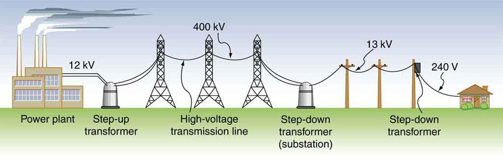
Transformers adjust electrical voltages at different stages of the power grid. Electricity is produced at power plants at voltages typically between 10 and 30 kilovolts (kV). For long-distance transmission, the voltage is increased to very high levels, often 230 kV to 765 kV, and sometimes even higher for special long-distance HVDC lines, to reduce energy losses.
When electricity reaches a regional substation near the point of use, the voltage is stepped down and sent through local distribution lines at about 5 to 25 kV. Finally, smaller transformers reduce the voltage again to the levels needed for homes and businesses, such as 120-240 volts for residences or 208–480 volts for commercial and industrial users.
High voltage is great for moving electricity efficiently over long distances, but it’s not safe to use directly in neighborhoods or buildings. Very high voltage can jump through the air (arc), overheat equipment, and seriously injure people. That’s why the grid includes multiple transformers and substations: they gradually lower the voltage to safe levels before it reaches homes, schools, and other places where people live and work.
Key Terms
Transmission Lines: High-voltage lines that move electricity long distances.
Distribution Lines: Lower-voltage lines that bring electricity to homes and buildings.
Transformer: A device that changes (steps up or steps down) voltage.
Substation: A facility where voltage is transformed and electricity is routed.
Voltage: The electrical “pressure” that pushes electrons through wires.
Grid: A system of connected power plants, lines, and equipment that delivers electricity to users.
Procedure
- Set-Up
- Decide whether students will work on this project individually, in pairs, or in larger groups. Provide each student or student group with a copy of the Student Handout.
- Arrange yarn, scissors, and tape on a materials table for student access.
- Introduction
- Direct student attention to the first part of the Student Handout that shows a diagram and explanation of the Electrical Power Transmission System.
- Ask a guiding question:
- What happens at each stage of the grid?
- Why does voltage change as electricity moves through the system?
- What do you notice about where high vs. low voltage is used?
- Guide students to the materials’ table and introduce the project using the Student Handout.
- Electric Grid Activity
- Starting with the poster paper or cardboard, students sketch their electric grid, creating transmission and distribution pathways.
- Students label all the required elements from the Electric Grid Components Table.
Required Electric Grid Components Table
| Component | Quantity | Notes |
|---|---|---|
| Power Plants | 2-3 | Label energy sources (e.g., natural gas, solar, hydro, etc.) |
| Step-Up Transformers | 2-3 | One per power plant |
| Transmission Lines | 3-4 | Red yarn; long distance |
| Regional Substations | 2-3 | Connect to population areas |
| Distribution Transformers | 3-5 | Step down to safe voltages |
| Medium Voltage Lines | 2-3 per substation | Yellow yarn |
| Low Voltage Lines | 1-2 per transformer | Green yarn |
| Houses | 6-10 | Residential loads |
| Schools | 1-2 | Higher-demand buildings |
| Commercial Buildings | 4-6 | Mixed energy needs |
- Using the correct yarn colors, students create transmission and distribution pathways, from the power plant to the end receivers (house, school, commercial building).
- Students add a key to the yarn colors, title their electric grid, and ensure all components are visible and labeled.
- Reflection
- Display finished designs around the room. Conduct an optional gallery walk for students to give each other feedback.
- Direct students to complete the reflection questions in the Student Handout.
Assessment Rubric
(also included in Student Handout)
| Criteria | Excellent | Proficient | Developing |
|---|---|---|---|
| Grid Components | All required components included, clearly labeled, and accurately represented. | All required components included, mostly labeled and accurately represented. | Missing or unclear components or labels. |
| Voltage Representation | Yarn colors used correctly throughout with accurate voltage transitions. | Mostly correct yarn usage throughout with minor errors. | Several inaccuracies with voltage transitions or color use. |
| Organization & Design | The layout is neat, logical, and easy to follow. | The layout is mostly neat, logical, and clear. | The layout is difficult to follow or incomplete. |
| Reflection & Reasoning | Choices are explained clearly and demonstrate strong understanding of main concepts. | Choices are explained clearly and demonstrate understanding of main concepts, with minor gaps. | Explanations show partial or limited understanding of main concepts. |
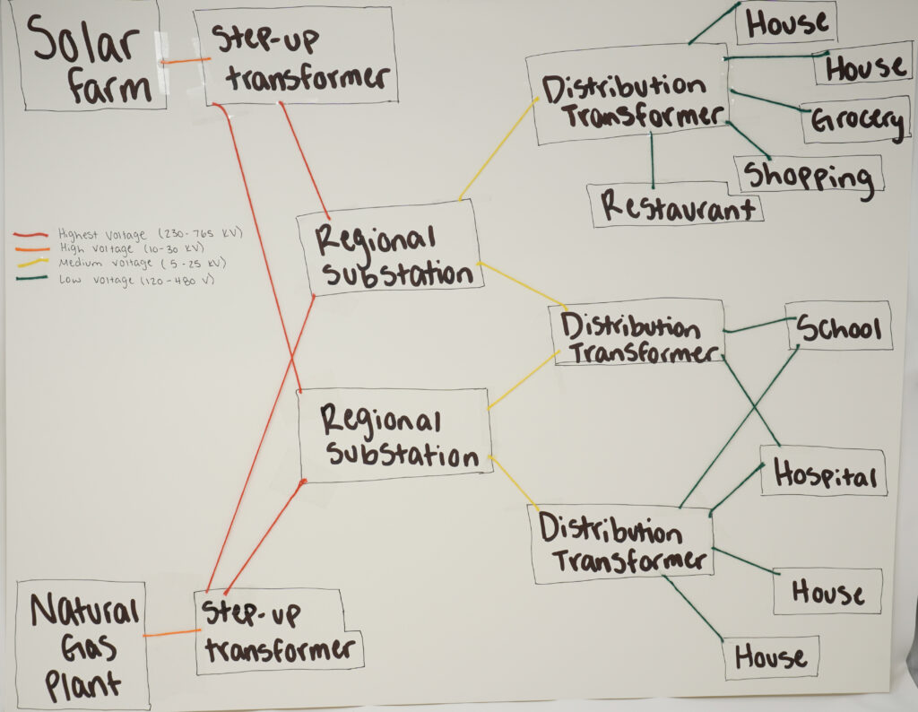
Student Example