Introduction
In this lab, students will work individually or in groups to create and test parallel and series electrical circuits, and discover how they are alike and different. Each step requires careful reading, precision in following instructions, and critical thinking and problem-solving as they observe the results. Students will also learn about conductors and insulators, and test various materials to determine their role in an electrical circuit. Extension activities focused on solving Ohm’s Law math problems and understanding simple circuit diagrams are also included.
Student Objectives
Students will be able to
- Construct and test both series and parallel circuits and correctly identify the effects of component placement on circuit functionality.
- Distinguish between conductors and insulators by testing everyday materials and observing whether the circuit is complete when each material is used.
- Apply Ohm’s law to solve problems involving voltage, current, resistance, and power in simple circuit scenarios.
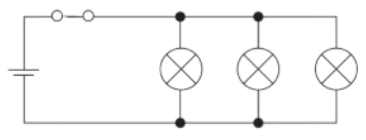
- Read and draw basic circuit diagrams using standard electrical symbols including representation of power cells, wires, switches, and loads (such as light bulbs), for both series and parallel circuits.
Materials
- Student Handout
- 5mm LED light diodes – 3-5 per individual/group for the first test, and an additional 3-5 for the remaining tests. Note: Diodes used for the first test will light up briefly, so groups will need to burn out a few diodes to observe the spark.
- 9-volt battery – 1 per individual/group.
- Play-Doh – 1 pack per individual/group.
- Pair of alligator clips – 1 per individual/group.
- Paper clips – 2 per individual/group.
- Popsicle stick – 1 (two halves) per individual/group.
- Plastic straw – 2 pieces per individual/group.
- Pennies – 2 per individual/group.
Answer Key
The Student Guide contains the Play-Doh Circuits Hands-On – Student directions and questions.
Part 1: Testing a Parallel Circuit Answer Key
1.3A. positive, anode
1.3B. negative, cathode
1.7A. Yes.
1.7B. Answers will vary. (Example: I think the second diode will not light up if placed in the Play-Doh incorrectly, but the first diode will stay on.)
1.7C. Answers will vary. (Example: The second diode will not light up because the positive current will not be connected to the positive lead of the diode (the anode), and the negative current will not be connected to the cathode.)
1.8A. Only one.
1.8B. The one that was flipped.
1.9A. Yes.
1.10A. Only one.
1.10B. The one that was flipped.
1.10C. A. Stay on.
Part 2: Testing Series Circuit Answer Key
2.3A. Answers will vary. (Example: I think that the second diode will not light up if placed in the Play-Doh incorrectly, and the first diode will also go out.)
2.3B. Answers will vary. (Example: When inserted incorrectly, the second diode will break the connection of the electric current, causing the first diode to also go out.)
2.3C. Both.
2.3D. Neither.
2.5A. Yes.
2.5B. B. It got weaker.
2.6A. All the lights
2.6B. Neither.
2.6C. B. will go out
2.6D. A. It gets weaker.
2.6E. Answers will vary. (Example: In a parallel circuit, each diode has its own path for the electric current to flow. When one diode is flipped, the current for that diode is blocked, but the others stay on because the current is still flowing. In a series circuit, the current is flowing in one line through each diode. If one diode is flipped, the electric current for the whole circuit is blocked, so all the diodes go out.)
Part 3: Testing Conductors & Insulators Answer Key
Make a prediction. Student answers will vary.
Correct Response: Penny (Conductor); Plastic Straw (Insulator); Wood (Insulator); Paper Clip (Conductor)
3.2A. Yes.
3.2B. Conductor.
3.2C. Answers will vary. (Example: When the diode leads connected to the pennies, the diode lit up, showing that the electric current flowed through the pennies.)
3.3A. No.
3.3B. Insulator.
3.3C. Answers will vary. (Example: When the diode leads connected to the plastic, the diode did not light up, showing that the plastic blocked the electric current from flowing.)
3.4A. No.
3.4B. Insulators.
3.4C. Answers will vary. (Example: When the diode leads connected to the wood, the diode did not light up, showing that the wood blocked the electric current from flowing.)
3.5A. Yes.
3.5B. Conductors.
3.5C. Answers will vary. (Example: When the diode leads connected to the paper clips, the diode lit up, showing that the electric current flowed through the paper clips.)

3.5D. Series 3.5E. Parallel 3.5F. Series 3.5G. Parallel
Part 4: Ohm’s Law – Math Activity Answer Key
4.1
V = I x R
2A x 5Ω = 10V
4.2
R = V / I
12V / 3A = 4Ω
4.3
Answer: I = V / R
10V / 20Ω = 0.5A
4.4
R = V / I
15V / 0.5A = 30Ω
4.5
20Ω + 30Ω = 50Ω (total resistance)
4.6
I = V / R (total)
10Ω = 30Ω = 40Ω
20V / 40Ω = 0.5A
4.7
P = V2 / R
202 = 400V
400V / 5Ω = 80W
4.8
P = V2 / R
122 = 144 V
144V / 4Ω = 36W
Part 5: Introduction to Circuit Diagrams Answer Key
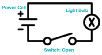
5.2 Answers will vary. (Example: The light bulb is currently “off.” The electric circuit is open, blocking the current from flowing through.)
5.3
Example (closed switch)
5.4
Example
5.5
Example