
Introduction
A circuit is a device that allows electricity to flow through it, usually to power other devices. Every complete circuit must have a power supply or source – for example, a battery. In this lab, you will create and test simple circuits made with a battery, wires, and bulbs.
Objectives
- To discover how a parallel circuit works
- To discover how a series circuit works
- To discover the difference between a conductor and an insulator
Materials
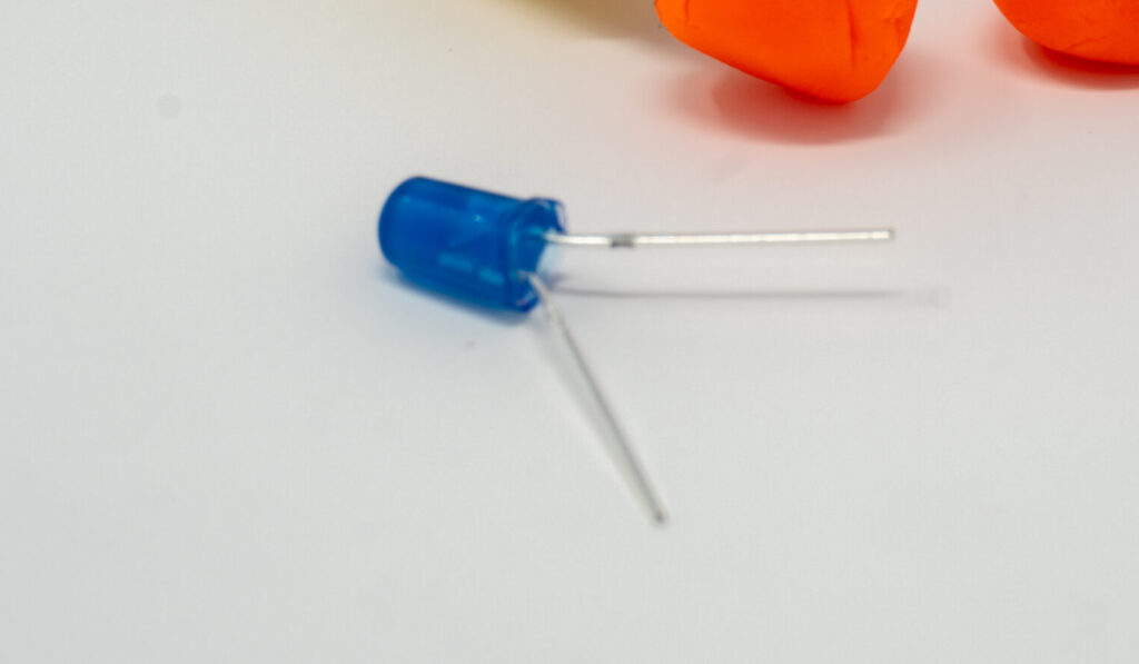
- 5mm LED light diodes – 3-5 per individual/group for the first test, and an additional 3-5 for the remaining tests.
- 9-volt battery – 1 per individual/group.
- Play-Doh – 1 pack per individual/group.
- Pair of alligator clips – 1 per individual/group.
- Paper clips – 2 per individual/group.
- Popsicle stick – 1 (two halves) per individual/group.
- Plastic straw – 2 pieces per individual/group.
- Pennies – 2 per individual/group.
Instructions (Parts 1-3)
Part 1: Testing a Parallel Circuit
Step 1
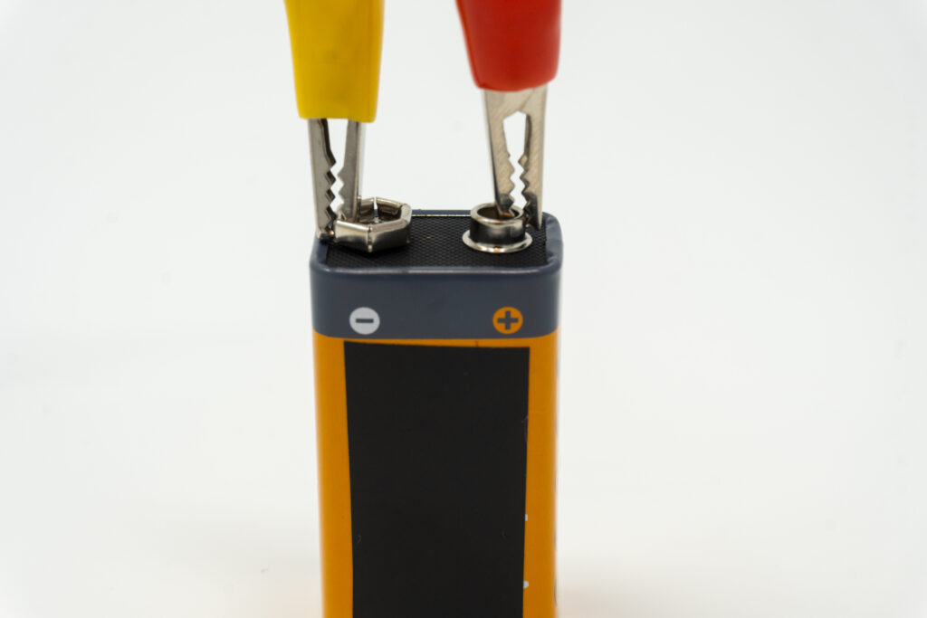
Take one of the alligator clips and clip one end to one terminal of the battery. Take the second alligator clip and clip one end to the second terminal. For the remainder of the experiment, you will not be moving or switching these clips. They will remain in place.
Observe that one alligator clip is connected to the positive (+) terminal of the battery, while the other is connected to the negative (-) terminal. This is important for later.
Step 2
Get an LED diode and test the light to see which lead is positive (+) and which is negative (-). To do this, take the ends of each alligator clip not touching the battery, and attach one on each lead, or wire, of the diode.
Important: If the diode doesn’t briefly light up, disconnect the alligator clips from the diode leads (wires), NOT at the battery terminals. Reattach the leads to the clips opposite from your original test.
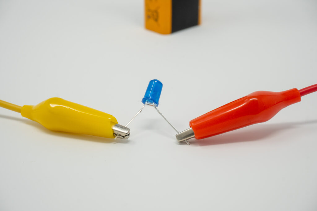
Also, because of the strength of the battery’s current, your diode will likely light up only for a second before burning out, so watch carefully!
Answer questions 1.3A and 1.3B in the Student Questions section that follows the instructions.
Step 3
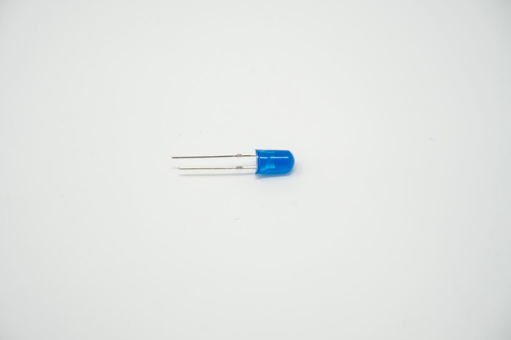
You will notice that one lead is longer than the other.
- When the diode lights up, observe which diode lead is connected to the clip leading to the negative (-) terminal of the battery and which diode lead is connected to the clip leading to the positive (+) terminal of the battery.
- The positive lead of the LED diode is known as the anode (+). The negative lead is known as the cathode (-).
Step 4
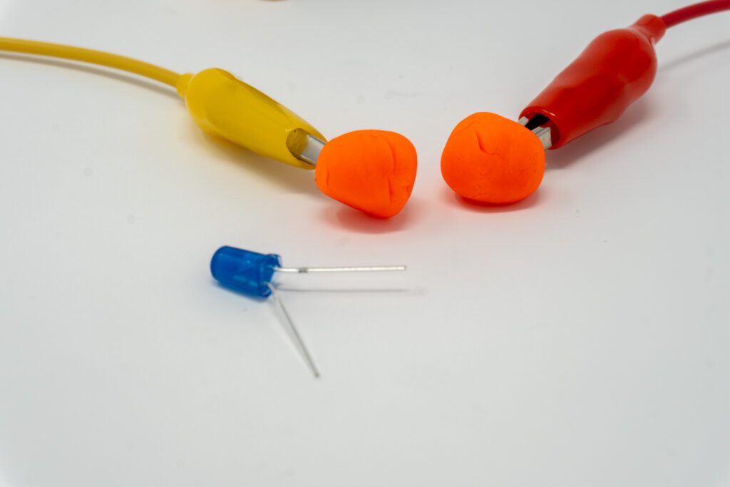
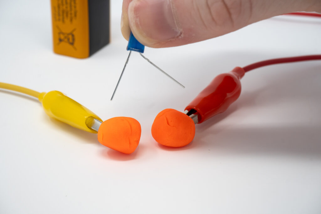
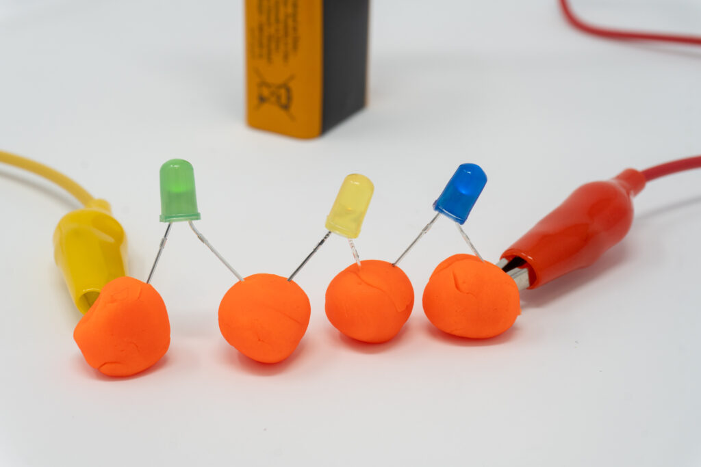
Disconnect the alligator clips from the LED diode (NOT the battery). Next, make two oval shapes out of the Play-Doh. Put one alligator clip in each one.
Your setup should now resemble the image on the right.

Observe: The wire that is attached to the positive(+) terminal of the battery is your positive wire. Once the metal part of the alligator clip is put into the play-doh, that piece of play-doh is now “positive” as well. The same with the negative(-) battery terminal wire. If you stick the negative wire into the play-doh, you will now have a “negative” play-doh.
Step 5
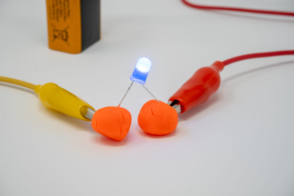
Bend the LED diode leads so that they can stick into the Play-Doh.
Step 6
Stick the positive lead (anode) of the LED diode into the positive Play-Doh. Then, stick the negative lead (cathode) of the diode into the negative Play-Doh.
Important: If it doesn’t light up, you may have mixed up the LED diode leads. Try switching them around.
The play-doh acts as a resistor, reducing the current so that the diode lights up without burning out.
Step 7
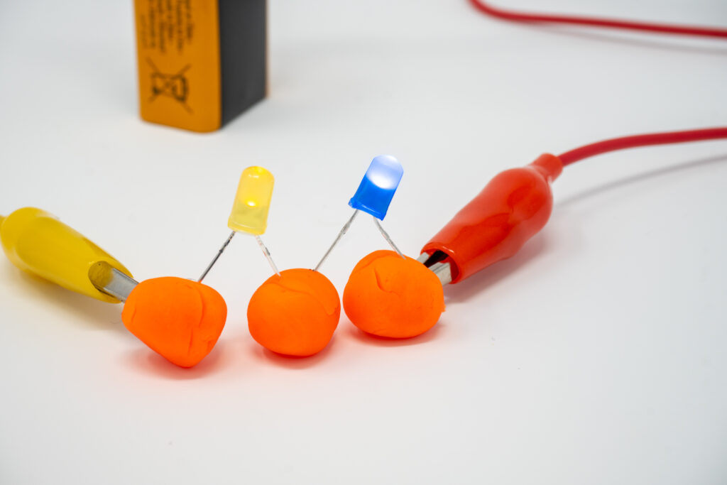
Once the diode is lit, add one more LED diode the same way you did the first, positive to positive, and negative to negative.
Answer question 1.7A.
Answer questions 1.7B and 1.7C to make and explain a hypothesis for what will happen if a second diode is placed in the play-doh incorrectly.
Step 8
Leave the first LED diode correctly inserted into the play-doh terminals. Switch the second LED around so that the positive lead is in the NEGATIVE play-doh and the negative lead is in the POSITIVE play-doh.
Answer questions 1.8A and 1.8B.
Step 9
Now switch the second diode back to the correct position, with the positive lead in the positive play-doh and the negative lead in the negative play-doh. Add a third diode in the correct position.
Answer question 1.9A.
Step 10
Now switch just the last (third) diode, so that it is incorrectly placed.
Answer questions 1.10A and 1.10B.
Extend Your Thinking. You just created a parallel circuit.
Choose the correct answer for 1.10C.
Part 2: Testing Series Circuit
Step 1
Go back to the original setup with one LED diode in two pieces of play-doh. Make sure it lights up!
Step 2
Make a separate piece of play-doh shaped just like the others. You should have three pieces of play-doh now. Arrange the play-doh so that the first and last pieces are connected to the alligator clips, with one by itself in the middle.
Step 3
Add two LED diodes, but this time one lead of the bulb should be inserted into the alligator clip play-doh, while the second lead of the diode should be inserted into the middle piece of play-doh.
Important: Make sure the positive (+) lead (anode) of the first diode is connected to the positive play-doh, and the negative (-) lead (cathode) of the second diode is connected to the negative play-doh.
If it doesn’t light up, double-check that the diode leads are connected to the right wires. When done correctly, both diodes should light up.
Important: Make sure that the three pieces of play-doh are NOT touching each other.
Answer questions 2.3A and 2.3B to make a hypothesis and explain what you think will happen if one LED diode is put in the play-doh incorrectly.
Test Your Hypothesis.
Switch the second bulb around so that the leads are inserted incorrectly.
Answer questions 2.3C and 2.3D.
Step 4
Now make one more piece of play-doh, so that you now have four pieces altogether. Arrange the pieces of play-doh, so that the pieces on each end are attached to the alligator clips, with two in the middle.
Step 5
Add three LED diodes, being careful to insert the positive and negative leads accurately. It should look like this.
Important: If it doesn’t light up, carefully check the diode leads and switch them around if necessary.
Answer questions 2.5A and 2.5B.
Step 6
Switch the LED diode around so that it won’t light up.
Answer questions 2.6A and 2.6C.
Extend Your Thinking
We just made a series circuit.
Answer question 2.6C and 2.6D.
Challenge Reflection Question.
Answer question 2.6E to reflect on how flipping a diode in a parallel circuit has a different effect than flipping a diode in a series circuit.
Part 3: Testing Conductors & Insulators
Read the Definitions.
Some materials allow electricity to flow through them.
They are called conductors.
When electricity flows through a conductor to a device, the device will turn on, since the conductor is allowing the electricity to flow through it.
A metal wire is an example of a conductor.
Some materials do not let electricity flow through them.
They are called insulators.
When electricity tries to flow through an insulator to a device, the device will not turn on, since the insulator is not allowing the electricity to move through it.
Paper is an example of an insulator.
Make a Prediction
Answer question 3.1 by filling out the table.
Step 1: Test Your Prediction
Go back to the original setup with two pieces of play-doh and one LED diode (make sure it lights up).
Step 2
Take the alligator clips OUT of the play-doh. Then insert a penny into each piece of play-doh and connect the alligator clips to each penny.
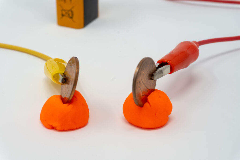
Answer questions 3.2A – 3.2C.
Step 3
Disconnect the alligator clips. Then, remove the pennies and replace them with pieces of plastic straw. Connect the alligator clips to each piece of plastic straw.
Answer questions 3.3A – 3.3C.
Step 4
Disconnect the alligator clips. Then, remove the plastic straws and replace them with pieces of wood.
Answer questions 3.4A – 3.4C.
Step 5
Disconnect the alligator clips. Then, remove the pieces of wood and replace them with paper clips. Connect the alligator clips to each paper clip.
Answer questions 3.5A – 3.5C.
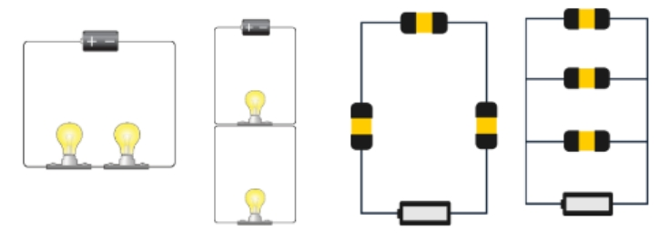
Identification Challenge.
Below are both parallel and series circuits.
Review the images, then answer questions 3.5D – 3.5G to identify each type of circuit.
Student Questions (Parts 1-3)
Fill in the blanks (positive or negative / anode or cathode)
1.3A. The longer wire is the _____________________________ lead, known as the _________________________.
1.3B. The shorter wire is the _____________________________ lead, known as the _______________________.
1.7A. Did both the bulbs light up? ______________________
1.7B. Make a Hypothesis: We know that if the positive lead of the light bulb is put into the negative play-doh, while the negative lead of the bulb is put into the positive play-doh, the diode won’t light up. What do you think will happen if the first diode is placed in the play-doh correctly, but we put the second diode in the play-doh incorrectly?
1.7C. Explain Your Hypothesis:
1.8A. Did both lights go out, or only one? ___________________________
1.8B. If only one, which one? The original, or the one you flipped? ___________________________
1.9A. Did all three lights stay on? ______________________________________
1.10A. Did all the lights go out, or only one? ______________________________________
1.10B. If only one, which one? The original or the one you flipped? ______________________________________
1.10C. In a parallel circuit, if one light “goes out,” the rest of the lights will:
- Stay on.
- Go out.
- Stay on or go out, depending on how many lights there are.
2.3A. Make a Hypothesis: Once again, what do you think will happen this time if one bulb is in the play-doh correctly, but we put the other one in the play-doh incorrectly?
2.3B. Explain Your Hypothesis:
2.3C. Did both lights go out, or only one? ______________________________________
2.3D. If only one, which one? The original one, or the one you flipped? _____________________________________ (You can say neither if both went out)
2.5A. Once they are connected, do all the bulbs light up? _____________________________________
2.5B. What happened to the strength of the light?
- It got stronger.
- It got weaker.
- It stayed the same.
2.6A. Did all of the lights go out, or only one? _____________________________________
2.6B. If only one, which one? The original, the one you flipped, or the middle one? ________________________ (You can say neither if they all went out.)
2.6C. In a series circuit, if one light “goes out,” the rest of the lights
- will stay on.
- will go out.
- will stay on or go out depending on placement.
2.6D. In a series circuit, what happens to the light as we add more diodes?
- It gets weaker.
- It gets stronger.
- It stays the same.
2.6E. Why is it that when you flip a diode in a parallel circuit, the other diodes stay on, but if you flip it in a series circuit, all the diodes go out?
3.1 Make a Prediction: Put a check mark in the column you think correctly identifies each material.
| Material | Insulator | Conductor |
|---|---|---|
| Penny | ||
| Plastic Straw | ||
| Wood | ||
| Paper Clip |
3.2A. Does the LED diode light up? _____________________________
3.2B. Is a penny an insulator or a conductor? _____________________________
3.2C. How do you know?
3.3A. Does the LED diode light up? _____________________________
3.3B. Is a plastic straw an insulator or a conductor? _____________________________
3.3C. How do you know?
3.4A. Does the LED diode light up? _____________________________
3.4B. Is wood an insulator or a conductor? _____________________________
3.4C. How do you know?
3.5A. Does the LED diode light up? _____________________________
3.5B. Are paper clips insulators or conductors? _____________________________
3.5C. How do you know?
Identify which is which by writing the name of the type of circuit (series or parallel) on the line below each picture.
3.5D. ____________________ 3.5E. _______________ 3.5F. ___________________ 3.5G. __________________
Part 4: Ohm’s Law – Math Extension Activity
Read About Ohm’s Law
Ohm’s Law is a simple rule that helps us understand how electricity works in a circuit. It explains the relationship between three important parts.
- Voltage (V): This is like the “push” that makes electricity move through a circuit. It comes from a battery or a power source.
- Current (I): This is how much electricity is actually flowing through the circuit.
- Resistance (R): This is how much something in the circuit slows down the electricity.
The rule is: Voltage = Current x Resistance
If you know any two of these (voltage, current, or resistance), you can figure out the third one. Voltage is measured in volts (V), current is measured in amperes(A), and resistance is measured in ohms (Ω).
For example:
- If you increase the voltage (the push), more current flows.
- If you increase the resistance (like adding something that makes it harder for electricity to flow), less current flows.
It’s like a math shortcut to figure out how electricity behaves!
Additionally, the formula to calculate Power is P = I x V.
Combining this with Ohm’s Law, you get P = V2 / R
Solve the Electricity Math Problems and Show Your Work
4.1 A circuit has a resistance of 5Ω and a current of 2A. What is the voltage across the circuit?
4.2 What is the resistance of a circuit if the voltage is 12V and the current is 3A?
4.3 A circuit powered by a 10V battery has a resistance of 20Ω. What is the current flowing through the circuit?
4.4 A resistor dissipates 15V when the current is 0.5A. What is the resistance?
4.5 A circuit has two resistors, 20Ω and 30Ω, connected in a series to a 10V battery. What is the total resistance of the circuit? (Hint: Total resistance is the sum of all resistors.)
4.6 What is the current in a circuit with two resistors (10Ω and 30Ω) in series, connected to a 20V battery?
4.7 A circuit contains a 5Ω resistor and a 20V power source. Calculate the power (Watts) dissipated by the resistor. (Hint: The formula for power is P = V2 / R)
4.8 A 12V battery is connected with a 4Ω resistor. What is the power used by the resistor? Use the power formula (P = V2 / R).
Part 5: Introduction to Circuit Diagrams – Extension
What is a Circuit?
A circuit is a path that electricity follows. For a circuit to work, it needs:
- Power Source – like a battery, to provide energy.
- Conductors – usually wires, to carry the electricity.
- Load – something that uses the electricity, like a lightbulb.
- Switch (optional) – to control the flow of electricity.
When the circuit is closed, electricity flows. When it is open, electricity stops.
Symbols in Circuit Diagrams
Circuit diagrams are like maps for circuits. Instead of pictures, they use symbols to show parts of the circuit. Even though wires are often flexible, a circuit diagram is kept very neat by making only rectangular shapes.
Here are a few common symbols:
| Components | Symbol |
|---|---|
| Power Cell | 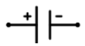 |
| Wire |  |
| Light Bulb | 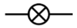 |
| Switch (closed) |  |
| Switch (open) | 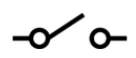 |
Identify the Components.
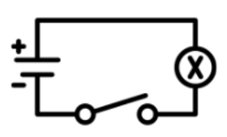
5.1 Look at the diagram to the right. Label the power cell, light bulb, and switch. Label whether the switch is open or closed.
Answer the Question.
5.2 In the circuit diagram to the right, is the light bulb currently “on” or “off?” Explain your response.
Your Turn.
5.3 Draw a circuit diagram with a power cell, light bulb, and a switch in the position it needs to be for the light bulb to be “on.”
Challenge: Draw a Series Circuit.
A series circuit is a type of circuit where all the parts (like light bulbs, batteries, or switches) are connected in one single loop. This means electricity has only one path to flow through.
- If one part of the circuit stops working, everything stops because the loop is broken.
- Example: If you have a string of holiday lights and one bulb goes out, all the lights might stop working.
5.4 Using the circuit diagram symbols above, draw a series circuit with at least three light bulbs, with an open switch.
Challenge: Draw a Parallel Circuit.
A parallel circuit is a type of circuit where the parts are connected in multiple paths. Electricity can flow through each path separately.
- If one part of the circuit stops working, the other parts can still work because electricity can flow through the other paths.
- Example: In your room, electric devices on the same circuit can work independently. If a light bulb goes out in a ceiling fan, the fan still operates.
5.5 Using the circuit diagram symbols above, draw a parallel circuit with at least three light bulbs, with a closed switch.